Process piping
Joint-aware routing for real fabrication choices
Butt-weld, socket-weld, threaded, and grooved rules affect takeout, cut lengths, joints, BOM, and PCF. Job setup keeps size, schedule, material, rating, and joint type with the model.
From field intent to fabrication layout
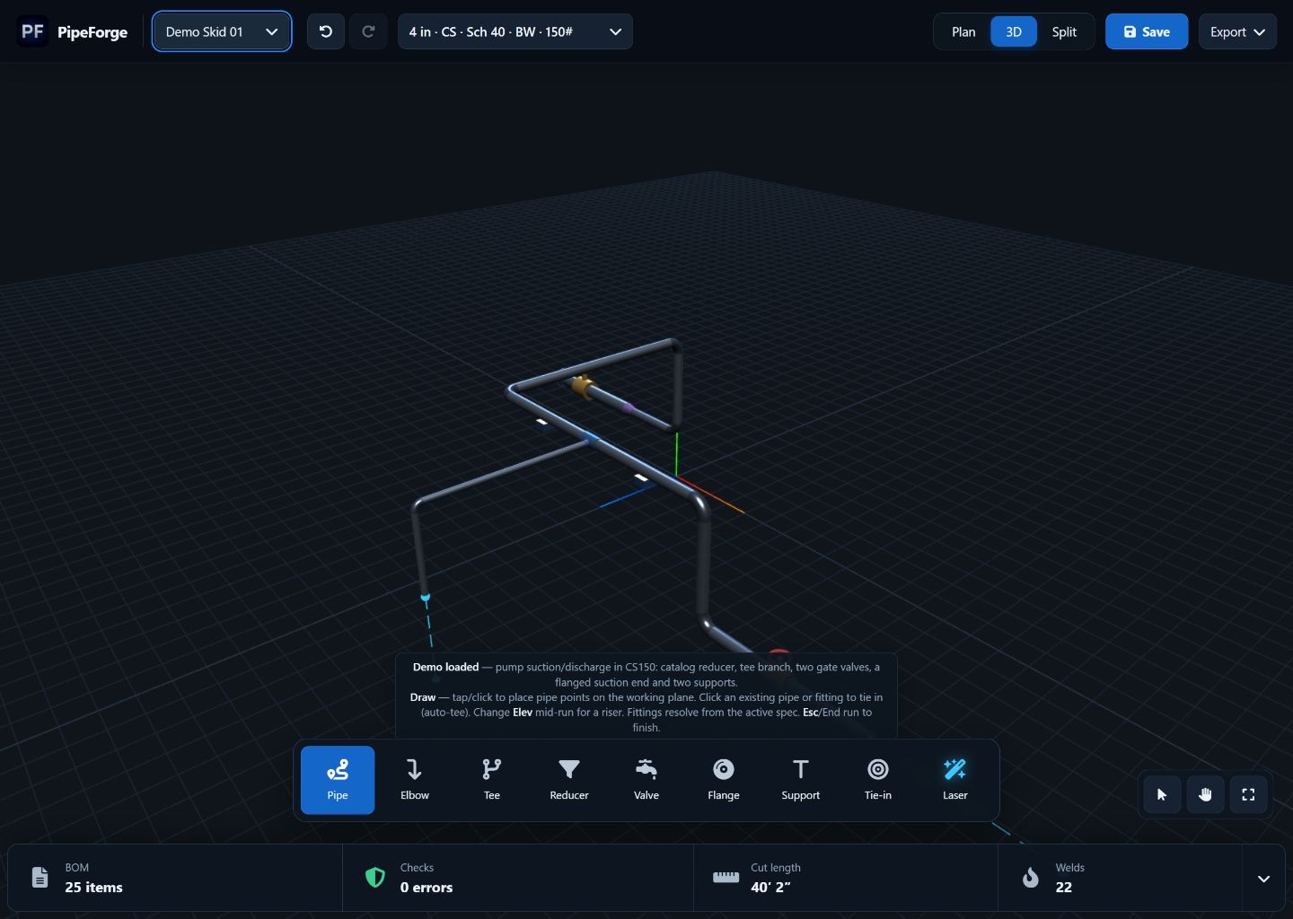
PipeForge gives piping teams a fast visual workspace for modular systems and skid layouts—route pipe, lock elevations and tie-ins, place fittings and supports, then hand structured information into the BIM and fabrication workflow already in place.
Focused planning software, not engineering approval. Support capacity, stress, code, weld procedures, and final fabrication release remain with project engineering and QA.
Built for fabrication teams
Process piping connects field measurements, design intent, detailing, metal fabrication, and prefabrication. PipeForge focuses on the information that needs to move cleanly between those groups.
Process piping
Butt-weld, socket-weld, threaded, and grooved rules affect takeout, cut lengths, joints, BOM, and PCF. Job setup keeps size, schedule, material, rating, and joint type with the model.
Prefabrication
Exact lengths, elevations, tie-ins, branches, checks, weld count, and material totals update from the model. That gives detailers a structured starting point instead of a loose collection of marked-up notes.
Support structures
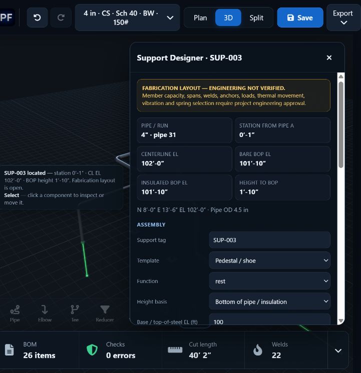
Place a support on a horizontal run and PipeForge records its pipe, station, coordinates, centerline, bare BOP, insulated BOP, and height from a named datum. Structural member choices stay in a separate fabrication workspace.
Design-build
A superintendent, foreman, estimator, or fabrication planner can establish the route and measurements. BIM specialists can then review structured geometry and focus on coordination, governance, and final deliverables.
The focused workflow
Choose the pipe size, schedule, material, rating, joint type, and job support palette.
Place straight runs and fittings. Enter exact feet-and-inches dimensions as the layout grows.
Use constrained rise/drop, custom angles, laser elevations, plumb references, and named tie-ins.
Capture station and elevation from the pipe, then detail the fabrication layout separately.
Check the BOM, cut lengths, weld count, support list, ISO preview, and PCF handoff data.
Support Designer
Support placement stays quick inside Pipe Design. The dedicated workspace opens only when fabrication detail is needed, so routing never turns into a structural-design form.
A fair comparison
Enterprise plant platforms solve a larger problem. PipeForge removes the unrelated project machinery when the immediate task is laying out one modular piping system.
| Program | Primary job | Typical setup | Best fit |
|---|---|---|---|
| PipeForge | Modular pipe/skid layout, field intent, support measurements, and fabrication-planning outputs | One focused job setup; browser workspace; portable local project file | Fast early layout and field-to-fabrication handoff |
| AutoCAD Plant 3D | P&IDs, specification-driven plant models, orthographic drawings, isometrics, reports, and BIM workflows | CAD-manager templates, project paths, specs/catalogs, desktop toolset, and optional collaboration administration | Formal plant authoring in an AutoCAD-centered workflow |
| AVEVA E3D | Data-centric, multidisciplinary design for complex capital, marine, power, and process projects | Unified Engineering environment, licensing/access administration, standards, and cross-discipline project data | Global teams, deep coordination, change management, and lifecycle handover |
| Hexagon Smart 3D | Enterprise facility design, constructability, modularization, managed deliverables, and lifecycle models | Site/database servers, permissions, catalog/model/report databases, and project administration | Large owner/EPC programs with governed enterprise infrastructure |
| CADWorx / OpenPlant | Specification-driven plant authoring, formal isometrics, BOMs, multidisciplinary and digital-twin workflows | Desktop CAD/suite installation, catalog/spec setup, project templates, and companion applications | Design-office workflows that need formal plant deliverables and connected disciplines |
Opening a modular project, capturing tie-ins and elevations, routing pipe, checking fabrication totals, and recording support dimensions without entering an entire multidisciplinary environment.
Whole-facility engineering, simultaneous multidisciplinary coordination, governed master data, formal drawing systems, digital twins, and long-term asset information management.
Prove it on real work
Use a small working session to compare PipeForge with the current early-layout process. The team keeps its existing BIM, engineering, fabrication, and QA gates. PipeForge earns its place only if the pilot shows a cleaner handoff.
Evidence and boundaries
Competitor capabilities and requirements were checked against vendor documentation on August 17, 2026. This comparison describes workflow focus, not feature parity. No productivity, cost, safety, or error-reduction percentage is claimed without a controlled pilot. PipeForge is not presented as engineering software or as a replacement for the project system of record. External PCF acceptance remains a formal pilot gate.